2021
Complex Structure Fire Claims
The investigation of losses typically requires the same methodology, therefore, we always use the methods outlined in the NFPA 921 Guide for Fire and Explosion Investigations. The methodology for fire investigations requires three steps, which have several mini-steps within themselves.
- Determining the origin of the fire – To do this, we use fire pattern analysis, consider witness information, and consider fire dynamics.
- Determining the cause – The cause could be related to equipment failure or product failure. It could also be related to human action or electrical failure.
- Finding circumstances for how the ignition source ignited the first fuel – This information may help you find potentially responsible parties. Moreover, it could help you determine the next steps for the insurance company.
Fire investigations often involve multiple parties. As such, it’s crucial to have more organization of the fire scene. As a result, there is more time to make the structure safe, and in the actual investigation, tough losses could take several days or weeks. There’s also a higher chance of working with public service agencies such as the Office of the Fire Marshal, local Fire Departments, the Ministry of Labor, and Police Departments. Sometimes our scenes may be spoiled by previous investigators, especially in cases with sizeable public exposure. We often find this in big cities and hazardous losses.
Complex fire loss standards
In large and complex losses, we must consider standards ASTM E1188 and ASTM E860, amongst others.
- ASTM E1188 – The standard practice for collecting and preserving information and physical items by a technical investigator.
- ASTM E860 – The standard practice for examining and preparing items that may become involved in criminal or civil litigation.
Both standards and the NFPA 921 are guides to preserving evidence, destructive or nondestructive testing, and evidence destruction. The standards set guidelines so that all parties interested in the loss have the same opportunity for evidence examination in its original condition and location. If any party does not follow these guidelines, another party may bring an action of evidence spoliation against the offending party. And with large and complex losses, there is a higher chance of procedures not being followed.
The nature of large and complex losses means there’s potentially more information available. This information could be from first witnesses, CCTV camera surveillance, the Fire Department, the Fire Commissioner, and other agencies. Even the Building Department and Fire Code Reviews may provide further information on why fire spreads rapidly.
There are more complex systems we need to evaluate during losses. These systems provide more information that may support other evidence. Therefore, all available information must be taken into perspective.
Case Study 1: Municipal building fire

Figure 1: A bystander supplied photo of the fire
A municipal building experienced a total fire loss which cost over $5 million. Fortunately, the Fire Chief was familiar with the structure and knew where the fire was first observed before it spread throughout the building. As a result, the fire was first kept above the garage area.
The complexity of this loss comes from the fact that the roof was insulated with cellulose insulation above the ceiling level and how the fire spread across the top. Cellulose insulation uses a recycled paper product treated with boric acid, a fire retardant. The cellulose insulation is blown into the roof. While it is highly effective as insulation, it is not fireproof.
If there is an ignition source within the cellulose insulation, it smokes. That smoldering front travels through the insulation and encompasses the whole ceiling, which happened in this case.
Details supplied indicated that some maintenance work was done over the garage, where the fire started. The garage area remained the only section after the fire; the rest was taken down during the fire suppression activities. Another complication, in this case, is that snow covered the fire scene, as shown in figure 2. This made it more challenging to investigate.
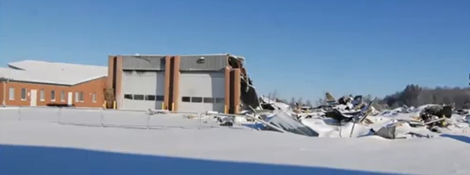
Figure 2: The condition of the building at the time of the investigation
Initial observations
Due to his familiarity with the building and the ignition point, the Fire Chief directed his crews to preserve the garage bays for fire investigation purposes. Figure 3 shows a fire pattern in the vertical metalwork, which seems to center around a hole for the outlet of a radiant tube heater.
It appeared that the hole was related to the fire, but we received information that the radiant tube heater was not operational before the fire. The hole can be seen on the top right corner of the left garage door.

Figure 3: The garage bay after the fire.
Figure 4 below shows the side of the building. We saw damages at the top of the wall, but we did not evaluate the rest of the building. The location of this damage indicated that the fire possibly started higher up.
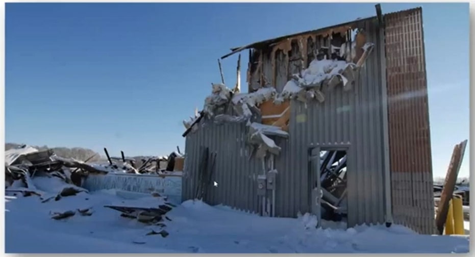
Figure 4: What remained of the left corner of the garage bay.
Preliminary findings and analysis
To get a clear view of the garage doors, we removed the remaining part of the roof using heavy equipment. This helped us visualize the fire damage in the area.

Figure 5: The area where witnesses first saw the fire.
The metalwork on the overhead garage door was still there despite physical damage. However, the wood structures behind the metalwork with the insulation were gone (figure 5).

Figure 6: Fire Department TIC images.
The Fire Chief provided the Thermal Imaging Camera (TIC) images in figure 6. TIC allows firefighters to find out where the most significant amount of heat is to concentrate their efforts on fighting the fire in those areas. The left-hand side image is looking towards the top of the garage door.
The scale on the side of the image shows the corresponding color and temperature. For example, on the scale in figure 6, anything dark is under 150ºC. Any area above 150ºC turns yellow. As the temperature goes above 300ºC, it turns orange, then red when it exceeds 450ºC. The deep red areas indicate that the temperature there was 650ºC.
The little square in the middle of the picture shows the actual temperature that the infrared camera was reading (382ºC). Through the TIC images, we observed that the top and middle plates were burning intensely during the fire.
The combustion chamber for the radiant tube heater and the exhaust tube connected to the hole above that garage door was gray, indicating that they were not hot. It supported the assumption that it was not operating before the fire. We probably would have seen some residual heat from it if it were working.
The image on the right in figure 6 shows the same area after water was poured over the fire. There was a significant decrease in temperature in the fire’s origin, although some residual heat was still above the ceiling. These images were instrumental in providing origin information for the fire. These are not the only two images that we received. There were images of the rest of the building, but this was the only area that contained high heat, meaning it was the fire’s origin.
Figure 7: Remains of the combustion chamber for the radiant tube heater.
We examined the entire remains of the radiant tube heater and found no evidence of failure or heat patterns. We also looked at the electrical systems to search for potential electrical causes. Our examination of all the electrical wiring in the origin area did not reveal any evidence of failures.
Conclusion
It was reported that the garage door was repaired on the evening before the fire, and an arc welder was used for welding the track to the angle iron metal piece against the door. Arc welding heats steel to melting temperatures and emits sparks and molten slag, a competent condition source for several building materials used in this building.
After considering all the potential ignition sources, we concluded that the most likely competent ignition source was the arc welding that the contractor conducted on the evening before fire discovery.
Lessons learned
- Be systematic in your investigations.
- Stick to the process.
- Consider all the hypotheses.
- Go through the process of elimination.
- Utilize all sources of information.
Case study 2: Condominium complex explosion

Figure 8: The condominium complex before the explosion.
An explosion occurred in a two year old, nine story condominium tower. The explosion happened in the parking garage, which was extended beyond the perimeter of the high-rise building. The total property loss was over $10 million, and over 200 unit owners were out for months while the building was being repaired.
At about 2:27 am, the superintendent, who lived in the downstairs units close to the garage, heard a huge bang. Six seconds later, there was a second colossal bang. He saw his wall and floor shapes bulge inward towards him, and the floor and walls shook. Several fixtures on his wall fell, and the electric power to his unit went off.
Initial observations
The explosion appeared to have carried through several areas in the building. An inspection of the roof revealed air vent duct deformation from the blast. Additional physical damages included:
- The toppling of concrete block walls in the main electrical room in the garage.
- Fire doors were blown off their hinges in the garage and several stairways.
We initially thought that this was a diffused gas leak or explosion. However, the pad-mounted transformer that fed the building was located outside, near the garage. In addition, there was an underground duct bank from the transformer that conveyed power underground through the sidewalk into the building and the garage area.
The fire scene had been investigated before our investigation by the Office of the Fire Marshal, and they removed the transformer for a better view of what was under it.
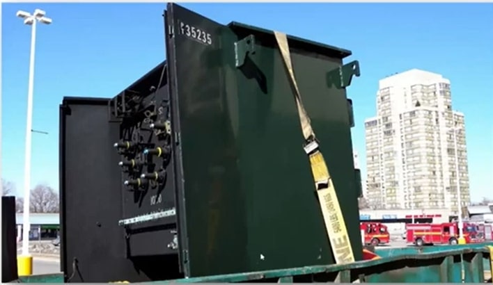
Figure 9: The removed pad-mounted transformer.
As indicated in figure 9, the transformer housing had significant deformation after the explosion. The doors on the front of the transformer were blown off and ended up about 100 feet away.
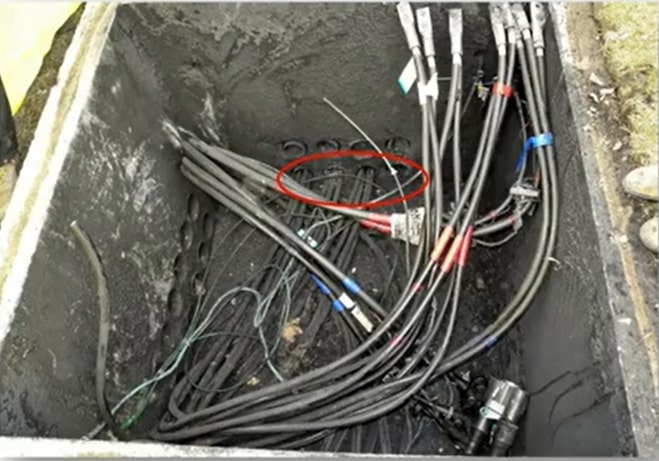
Figure 10: The uncovered transformer pit.
We uncovered the pit over which the transformer was mounted (figure 10) in the hole where the primary and secondary cables connected to the transformer. The secondary wires, which were on the low-voltage side, were 600 volts. The low voltage side had four feeds into the building through four 4-inch diameter ducts. One of the ducts was already pulled out by the Office of the Fire Marshal for Inspection.

Figure 11: Duct 1 conductors
The Fire Marshal’s Office placed conductors from the transformer pits on the sidewalk for further inspection. Our initial examination showed different areas with a bit of heat damage and a soot coating outside the insulation on the conductors.
Preliminary findings and analysis
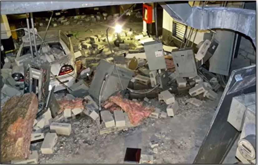
Figure 12: The main electrical room in the P1-level parking lot.
The concrete block electrical room wall was blown out from inside the electrical room outwards. You can see the debris field in figure 12. The projectile distances of the concrete block walls were 50 to 75 feet away. Some of the pieces of electrical equipment were hanging from their conduit, and wires were damaged. The switchboards were also damaged (figure 13).
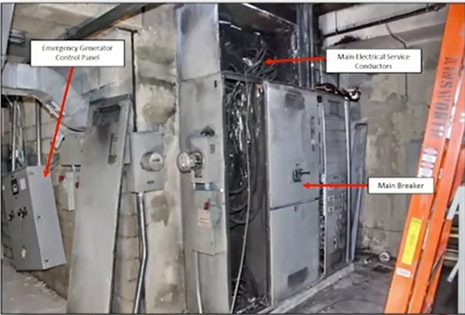
Figure 13: The switchboards on the opposite wall of the electrical room.
The building also had an emergency generator whose control panel got pushed off the wall. You can see this control panel on the left-hand side of the above image. The conductors, also marked in figure 13, came in from the transformer outside and connected to the main breaker.
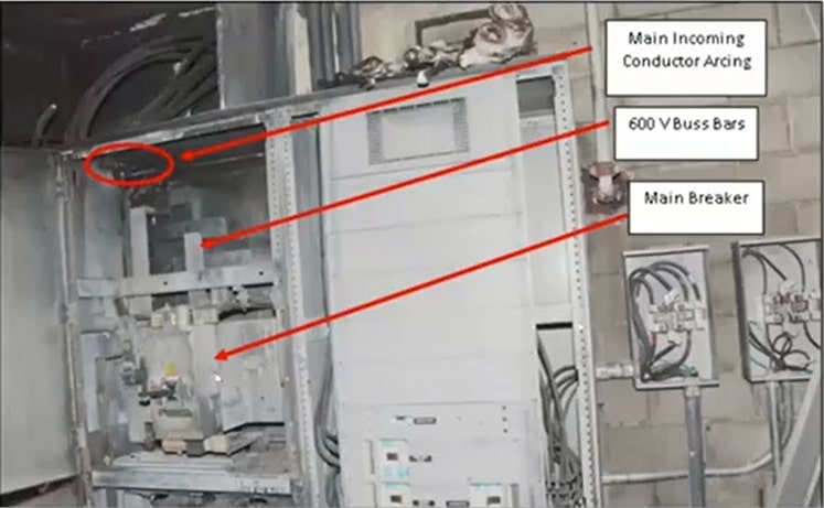
Figure 14: The main breaker and main breaker incoming 600V bus bars.
Figure 14 looks at the incoming conductors through the duct bank from the outside. They connected through the main breaker. Below (figure 15) is the Plan View of the electrical room. The blue lines represent those four incoming busbars that bring power from the transformer. They come into the back of the electrical panel board. The yellow line represents the electrical room outline.
The red arrows are explosion vectors that we placed. The size and direction of these explosion vectors signified the direction and intensity of the push from the explosion.
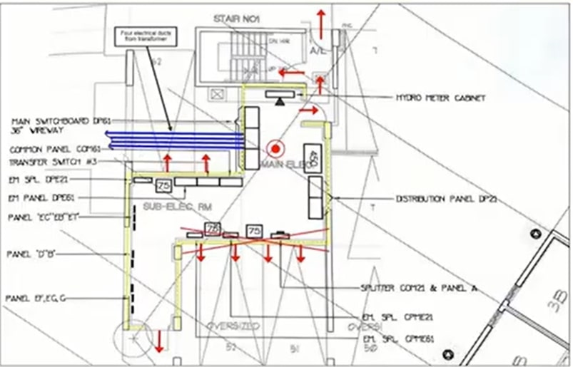
Figure 15: Plan View of the electrical room.
The explosion vector study determined that the explosion originated inside the electric room because the walls were pushed outwards. In addition, we noted doors that were deformed towards and into the staircase on the top side of the electrical enclosure. That staircase went up to the roof, and doors were deformed at the roof level as well. This information further confirmed that the explosion’s epicenter was the electrical room.
Now that we had the explosion origin, we wanted to determine why the diffuse gas was in the electrical room. We considered that it could have been from a leaking propane cylinder stored in the garage or a propane-powered vehicle in the garage that released flammable gas. However, we did not find evidence of propane-powered vehicles or propane cylinders.
We also considered that the explosion might have been caused by sewer gas. The electrical room had two floor drains in it, and sewer gas migrating through the floor drain in the electrical room could have collected in there and ignited from a switch, resulting in the explosion. But we know that floor drains contain traps. Typically, water in the traps can seal any migration of those sewer gases through the system.
Our investigation led us to the sprinkler room, which contained the trap priming system for all the P1 and P2 level area floor drains. All floor drains have a device that dribbles water into the floor drain and keeps water at the base of that floor drain that fills the trap and stops the migration of sewer gases. This building had a similar system, which is a building code requirement.
The flush tanks in figure 16 fill and automatically flush the water down into the manifold. Next, the manifold leads to other smaller lines that convey water. Each line goes to each separate floor drain and keeps that floor drain primed with water, which doesn’t allow the sewer gases to migrate.
Our examination of the floor drains, and the system revealed that it was all working correctly, eliminating sewer gas as the fuel for the explosion.

Figure 16: The main sprinkler room in P1 with trap priming systems.
The garage’s exterior wall facing the transformer had a concrete haunch that showed physical damage. This concrete haunch had four ducts coming in from the transformer outside and then up through the ceiling space to the main switch in the electrical rooms.

Figure 17: The north wall concrete haunch, showing soot and physical damage.
We pulled the rest of the conductors out of the other three ducts. We found a polyurethane foam that was stuck to the conductors. We measured where the foam would have been when the conductors were inside the duct, and we found that it was at the concrete wall inside the building, near the damaged concrete haunch.
Once we pulled the conductors, we shot an RF duct camera inspection video. It involved sending a drain camera into duct bank three.
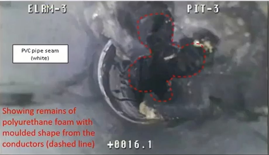
Figure 18: A still frame from the duct camera inspection video.
The dotted line in figure 18 outlines where the conductors were. We considered that the foam may have been polyurethane foam injected by contractors underneath the concrete slab of the sidewalk near the building. Keeping that in mind, we conducted Megger insulation testing on all the conductors we pulled out of the duct banks. A Megger test checks the insulation integrity on electrical wiring.
We put the conductors into a pool of water and applied a voltage of 2,500 volts from the Megger, and the Megger indicates whether that insulation is intact or not. The Megger test showed a breakdown of the insulation.
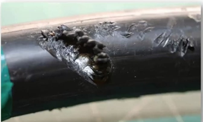
Figure 19: A microscopic image showing insulation damage.
We found spiral damage on the conductor. The aluminum strands within the conductor were exposed. The red phase conductor from duct three also showed spiral damage. We found similar damage on other conductors.
Finding this damage and the form, we excavated the conductors entering the P1 garage level through the concrete haunch. We didn’t find any foam beneath the sidewalk. So we started removing some of the concrete from the concrete haunch and found drill holes. Figure 20 (right-hand image) shows a close-up of the drill holes.

Figure 20: The damaged concrete haunch.
Conclusion
The drill holes had a stiff plastic applicator with foam inside. We found that after the construction of the building, the garage had water infiltration issues from a high-water table. So, the general contractor hired a subcontractor to waterproof the garage walls. The easiest way to do that was to drill holes from inside the garage to the outside and inject hyper hydrophobic foam, a polar polyurethane foam product.
During the process, the subcontractor also drilled through the concrete haunch, not knowing there were electrical cables inside. Unfortunately, in doing so, he damaged some of the wires with the drill. Over time, water entered the transformer pit, made its way through the conduit, wetted the area where the conductors were damaged, and while the water was making its way through the ducts, it picked up impurities. Those impurities included salts, dust, and other chemicals that made the water semi-conductive.
We concluded that the explosion was a result of electrolysis. Electrolysis is the separation of water molecules by using electricity. For example, H₂O is separated into hydrogen and oxygen by applying electricity to water. In this case, some electricity was lost into the water from the damaged cables. As a result, it generated gaseous hydrogen and oxygen. The two gases filled the electrical room and the transformer until the concentration of the two gases was sufficient to ignite a tiny spark from the activation of a switch. It caused the explosion.
When we looked at the rest of the garage, we found other walls with similar drill marks. The foam filling the walls in these areas was parched over and painted.
We concluded that the drilling conducted by the subcontractors damaged the incoming cables, which resulted in the leakage of electricity through water in the bus ducts, and the generation of flammable gases that eventually ignited and caused significant property damage from the explosion. The circumstances indicated that the general contractor was responsible for the loss.
Lessons learned
- Stick to the process, even in complex losses.
- Be systematic in the investigation.
- Follow up on all your leads for the evidence presented in the investigation.
A Litigator’s perspective on experts
Courts are usually not interested in opinions; they value facts and expertise. However, exceptions are made for expert testimony subject to several criteria being satisfied.
An expert’s opinion must be relevant, and its prejudicial impact on a party must not outweigh its probative value. It has to be necessary to assist the trier of fact, meaning it has to be outside the experience and knowledge of a judge or jury. There has to be an absence of an exclusionary rule of evidence, and of course, the expert has to be adequately qualified.
Scene investigation – Retaining your Expert.
In our line of work, it’s essential to pick an expert with proper qualifications. If you have a nuanced case, you must be careful about the expert you’re selecting. If you bring an unqualified expert witness to court, you risk having your entire case fall apart. So, take your time to find the right expert with all the necessary qualifications. The following steps will come in handy when you search for an expert:
- Involve your experts early
Get your expert involved as early as possible in your investigation. It is especially crucial during a fire loss as it will help you avoid scene spoliation. In addition, the multiple parties involved in such cases can lead to scene disruption. As such, it is incredibly crucial to get your expert out there as soon as possible.
- Look for experts with multiple competencies
When retaining an expert, you need to conduct a cost-benefit analysis. It means you need a multi-skilled expert for any case. Your expert must have the competencies that you need to deal with causation, whether it’s a fire loss or mechanical failure.
Competency is particularly essential for fire loss cases because the first arrival to a scene is the best time to gather evidence. Therefore, your expert must have competencies that go beyond investigating causation. For example, they must meet with witnesses, conduct additional research, find the area of origin, rule out electrical fault, or find smokers’ materials that have been carelessly discarded.
- Manage your cases
If you’re working at a desk and only deploying the resources, you need to manage your cases exceptionally well. For example, it is essential for first-party property adjusters investigating a loss because they usually send an engineer to deal with causation.
Get the engineer you retained to meet as many people as possible, get as much information as possible, and gather all witnesses’ names and contact details. Work with your investigator and emphasize the importance of gathering all the necessary information for the investigation. If it’s a significant enough loss, spend the money required to have them do additional work. That will help you gather evidence because scene investigation is critical to any case.
- Invest in your expert
Utilize and invest in your expert at the outset to help you understand the technical aspects of the case. Using the tools at your disposal and investing extra time to communicate your expectations is beyond invaluable in the long run. If you’ve got the resources and a case that’s worth enough money, invest in it. And your expert is your best investment. Build your knowledge and understanding of the case at the time of the loss if you can.
Desk reviews
All is not lost if you can’t retain an expert to attend a scene. You can have an expert for a desk review of all relevant evidence available. That would include scene investigation photographs provided by the other party, Fire Services records or other records of participating experts, information obtained from your insured, and witness statements from others.
Case study 1: Industrial fire loss spread case
This case was settled five or six years ago. It was an industrial fire spread case. Our insured had a neighboring industrial facility beside the fire. There was a lot of damage at the scene, making it difficult to gather evidence. A suspected halide light failure in the warehouse is pictured (figure 21).
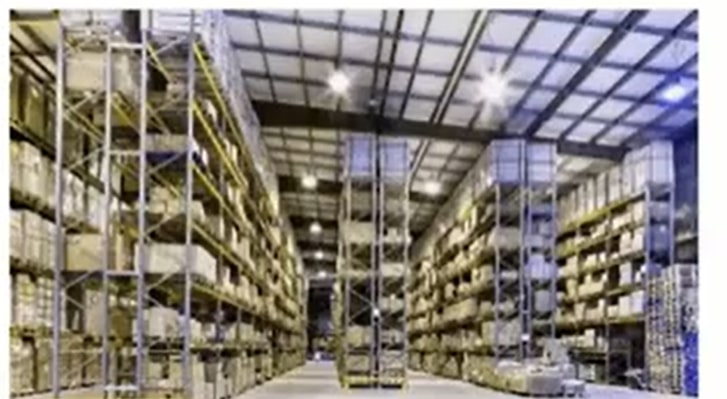
Figure 21: The warehouse
Preliminary findings and analysis
Our expert, on the scene, interviewed an electrical subcontractor who disclosed that installation had deviated from the permit drawings. They hardwired halide lights so that they could not be turned off. It was on the owner’s instructions. Halide lights are to be turned off at least every seven days for 6 hours to prevent overheating and accidental explosions.
Resolution
The deviation from permit drawings meant the halide lights were permanently energized. That fit in perfectly with the theory that one of the halide lights exploded, and hot filaments landed on cardboard boxes stored in the warehouse, thereby causing the fire. And so, we ended up settling that case. So, that one piece of information our expert gathered on the scene got us a settlement.
Scene investigations – Documenting the scene.
Documenting the scene might seem prosaic and unimportant, but it is a critical component of scene investigations. I have seen more than a few cases where there is no proper context for the entire scene that you’re dealing with.
It is essential to document the scene to provide as much spatial context as possible. Take a wide-angle shot from a distance, with more pictures as you approach the stage. That way, different areas of interest can be put into photographic context. If you need to retain an expert subsequently for a desk review, they will be better positioned to understand the scene.
Communicating with your expert
Assume that all your communications with your expert will become part of the record. We all deal with people regularly and often establish relationships to have nonprofessional discussions. However, it is crucial to avoid overly friendly communication when talking to your expert.
Keep your communication professional because it will likely be produced. If there appears to be a friendliness between the adjuster and the expert, it creates an unnecessary opening to challenge the expert’s impartiality.
If you have a statement that has been obtained during your investigation, do not produce the statement to your expert unless you are willing to waive privilege. The purpose of a statement is to refresh your client’s memory when you potentially re-interview them years later. Unfortunately, when stating you’re insured to your expert, you waive privilege, and that can never help your case.
Only take the critical parts of the statement that you want your expert to rely on to work around that. Then, in your instruction letter to your expert, tell them which facts to rely on when preparing their opinion. Then, you document those facts, which must be proven at trial. But privilege will be preserved, and your insured won’t be cross-examined on their statement.
Managing the scene before expert arrival
Preserve the scene in situ before your expert arrives. Ensure that whoever you instruct knows to preserve evidence until your expert arrives. You will not be explicitly faced with destruction, but you will have compromised proof, which is almost as bad.
Case study 2: Large fire loss
A cottage property in Muskoka experienced a significant fire loss. The property had a few elevation changes, and power was supplied underwater through a cable to a transformer. The energy from the transformer then went to a meter. A cable was laid to the panel inside the cottage from the meter.
The previous investigators concluded that the loss resulted from our client’s agent hitting the main power cable while undertaking final grading with a backhoe. As soon as he hit that meter, the place went up in flames, and the cottage was damaged entirely within half an hour.

Figure 22: Images of the scene
When we received the file, investigators prepared a final report based on one site investigation by investigators for each party the day after the loss. Evidence suggests that the power cable had been buried at an appropriate depth with caution tape at the proper level, but it was not determinative.
We were not convinced that the experts had covered all bases during the initial investigation. There were three or four different experts who had been retained by the builder, electrician, electrical subcontractor, our client, and the TSSA. All these experts were huddling around where the backhoe hit the power.
They all confirmed that the builder was present during the investigation. And he insisted that the insured had changed the elevation since they built the house. Granted, the insured elevated a parking lot since it was too steep. But that didn’t change the grading around the property, meaning it would have no impact on the cottage or surrounding areas.
Initial observations

Figure 23: A picture of the cottage before the fire loss
The circled part of the cottage in figure 23 shows the cable. The photo was taken in October 2010, and the cable was coming out of the foundation.
Below is a picture taken a bit later, after the builder had returned to put topsoil over the cables. We could tell from the surroundings that both figure 23 and figure 24 were captured in the same year’s fall. From figure 24, we could determine that the cable was not 18 inches below grade.

Figure 24: The cottage after topsoil was placed over the exposed cables.
When we showed the images to our client, he said none of the experts spoke to him, even though he was at the property with them. He said the cable was three inches or less below grade. The builders did not bury the cable to the proper depth. We realized that the initial report was premature and asked for the discovery evidence.
The scene photographs only contained specific areas. No wide-angle shots were showing the contour of the land.
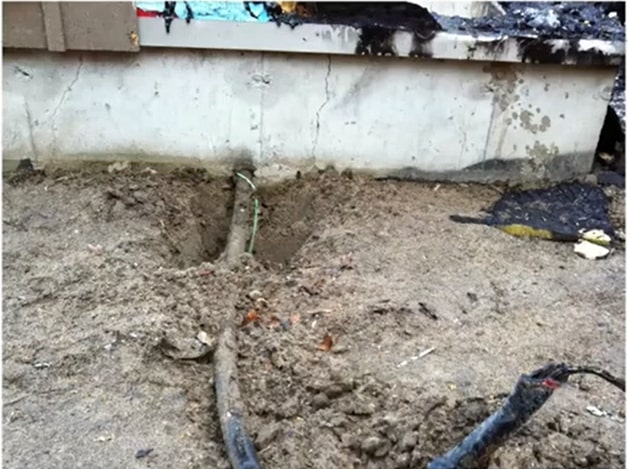
Figure 25: An image showing the cable after the loss.
The image in figure 25 was taken after the loss. There had already been some disruption, but the cable looked close to grade.
Resolution
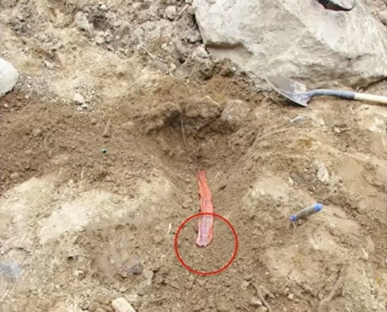
Figure 26: The caution tape.
We also found a photo of a cut caution tape taken when all the experts were investigating. When we asked the builder about the caution tape, he said the cable was buried and suggested that our client cut the caution tape while regrading his home. When we looked at more of the discoveries, we found an image with the cable tied up in a bit of caution tape. The cable had already been buried.
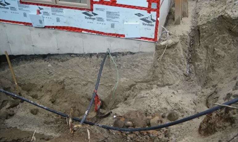
Figure 27: The dug-up electric cable with a pipe beneath.
When we asked the builder about this, he said the electric cable was dug up to lay a sewer pipe beneath it. So they had to dig up the entire area to lay the pipe, including the area with the electric cable. So when we presented all our findings to our expert, we managed to get a reasonable settlement. We took a case that would be closed, and we got a payment of approximately $500,000.
In Complex fire claims, small things can have a magnifying impact on the case as it moves forward. Therefore, you must not rush into things; give your expert wide latitude. But, most importantly, work with your expert. Communicate frequently and get your information early. If you understand your case well, you’re going to be the best asset you have to predict whether you’re going to have a recovery or a good defense to a claim. And the best way to do that is to leverage your experts’ expertise, scene knowledge, and evidence.
Origin and Cause: Choice Experts for Fire Claims and Property Damage
Our forensic experts have extensive experience conducting investigations, preparing reports, and testifying as expert witnesses in court. If you’re dealing with fire failure resulting in complex claims and property loss, call 1-888-624-3473 and we will conduct a thorough inquiry based only on facts and evidence.